We will explore the different components on the Arduino UNO board, one of the most popular boards in the Arduino family. It’s an excellent choice for beginners who want to dive into electronics and coding. While other boards may look slightly different, most Arduinos share the same core components, which we’ll examine in detail below.
Board Description
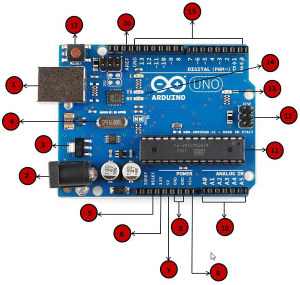
Power USB
The Arduino board can be powered via a USB cable connected to your computer. Simply plug the USB cable into the USB connection (1) to power up your board.
Barrel Jack
The Arduino can also be powered using the Barrel Jack (2), which allows you to connect the board directly to an AC mains power supply.
Voltage Regulator
The voltage regulator ensures that the Arduino board receives a stable voltage. It controls and stabilizes the DC voltages used by the board’s processor and other components.
Crystal Oscillator
The crystal oscillator helps the Arduino handle time-related tasks. The number printed on the crystal (16.000H9H) indicates a frequency of 16 MHz, which is essential for calculating time and executing commands.
Arduino Reset
You can restart your Arduino program by pressing the reset button (17) on the board. You can also connect an external reset button to the pin labeled RESET (5).
Pins
- 3.3V (6): Provides 3.3V output
- 5V (7): Provides 5V output
- GND (8): Several ground pins that can be used to ground your circuit
- Vin (9): Can be used to power the Arduino from an external source
Analog Pins
The Arduino UNO has six analog input pins (A0 to A5), which can read signals from analog sensors (e.g., humidity or temperature sensors) and convert them into digital values.
Main Microcontroller
The microcontroller (11) is the brain of the Arduino board. It varies slightly between different Arduino models but is typically an ATMEL microcontroller. You can find the IC type printed on the top of the chip, and further information is available in the IC’s datasheet.
ICSP Pin
The ICSP (12) is a small programming header used to connect to the microcontroller. It functions as an SPI (Serial Peripheral Interface), allowing communication with external devices.
Power LED Indicator
This LED lights up when the Arduino is powered. If the LED doesn’t light up, it indicates a power issue.
TX and RX LEDs
The TX (transmit) and RX (receive) LEDs (13) blink to show data being sent or received. These are located near pins 0 and 1, which are used for serial communication.
Digital I/O Pins
The Arduino UNO has 14 digital I/O pins (15), 6 of which can provide PWM (Pulse Width Modulation) output. These pins can act as digital inputs or outputs, driving components like LEDs, relays, and more. Pins marked with “~” can generate PWM signals.
AREF
AREF (Analog Reference) can be used to set an external reference voltage (between 0 and 5V) as the upper limit for the analog input pins.