Welcome to Maker Tech Lab! In this tutorial, we will build a simple traffic light system using an Arduino Uno. This project will help you understand how to control multiple LEDs with an Arduino to simulate traffic light signals.
Materials Needed

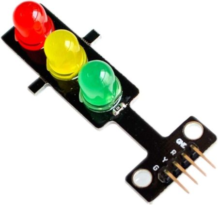
| Traffic light display Module Buy at Amazon |

| Arduino Uno Buy at Amazon |

| Breadboard Buy at Amazon |

| Jumper Wires Buy at Amazon |

| 220 ohm Resistor Buy at Amazon |
- Connect the LEDs (if you are using regular leds): Place the three LEDs on the breadboard. Connect the anode of each LED to a digital pin on the Arduino (e.g., pins 8, 9, and 10). Connect the cathode (shorter leg) of each LED to a 220-ohm resistor, and then connect the other end of each resistor to the ground (GND) on the Arduino.
- Connect the 3 Leds Traffic light display Module: Connect G,Y,R pins from traffic display module to Arduino (e.g., pins 8 (Red) , 9 (Yellow) , and 10 (Green) ). Connect GND to ground (GND) on the Arduino.
The Code
Here’s the Arduino code to control the traffic light system:
const int redPin = 8; const int yellowPin = 9; const int greenPin = 10; void setup() { pinMode(redPin, OUTPUT); pinMode(yellowPin, OUTPUT); pinMode(greenPin, OUTPUT); } void loop() { // Turn on the red LED and turn off the others digitalWrite(redPin, HIGH); digitalWrite(yellowPin, LOW); digitalWrite(greenPin, LOW); delay(5000); // Red light for 5 seconds // Turn on the yellow LED and turn off the others digitalWrite(redPin, LOW); digitalWrite(yellowPin, HIGH); digitalWrite(greenPin, LOW); delay(2000); // Yellow light for 2 seconds
// Turn on the green LED and turn off the others digitalWrite(redPin, LOW); digitalWrite(yellowPin, LOW); digitalWrite(greenPin, HIGH); delay(5000); // Green light for 5 seconds }
Explanation
- Pin Setup: We define the pins where the red, yellow, and green LEDs are connected.
- Setup Function: We initialize the LED pins as outputs.
- Loop Function: This function cycles through the red, yellow, and green LEDs, turning each LED on for a specific duration to simulate a traffic light sequence.
Uploading the Code
- Open the Arduino IDE.
- Copy and paste the code into the IDE.
- Select the correct board and port from the Tools menu.
- Click the upload button.
Conclusion
Congratulations! You’ve built a simple traffic light system using an Arduino Uno. This project is a great introduction to controlling multiple outputs and can be expanded to more complex systems. Stay tuned for more tutorials and exciting projects at Maker Tech Lab!
Happy making!